1959 BUICK WINDSHIELD WIPER – TWO SPEED
1-5 1959 BUICK WINDSHIELD WIPER DESCRIPTION AND OPERATION
General Description
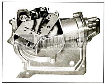
Electric powered windshield wipers replace the vacuum operated wipers used in previous years. See figure 1-14.
1959 Buick Windshield Wiper Motor
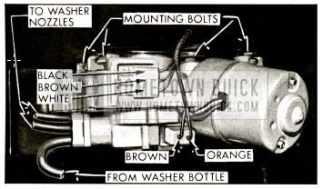
Single speed wipers are standard on 4400 and 4600 Series with the two speed Cam-O-matic available as an option. The Cam-O-matic is standard on 4700 and 4800 Series. 1959 Buick Windshield washers are standard on Cam-O-matic wipers and not available on single speed wipers except by dealer installed accessory. The Cam-O-matic motor is larger than and different in design from the single speed motor. It is equipped with a washer pump. The pump bolts directly to the bottom of the wiper motor assembly and is driven by the motor. The pump is relay actuated through the switch on the instrument panel.
To operate the 1959 Buick windshield washer, the button on the switch must be pushed in or forward. In so doing, the wiper switch knob is mechanically rotated by the button, to the slow speed position. After the washer has stopped, the knob must be manually turned back to the off position to stop the wiper blades. The blades always return to the park position when the switch is turned to off. If a faster wiper blade speed is desired, the knob should be turned all the way in a clockwise direction.
The single speed wiper switch has no button and is only a single position switch. When the switch is turned to the off position, the blades do not return to a full park position, but a few inches away from the reveal molding. See Section 1-E for service procedures on the single speed windshield wiper.
All motors are held to the upper cowl by four bolts. The bolts come in from above and thread into special nuts located in “T” slots on the top of the motor body casting. The nuts are mounted in rubber for quietness of operation. A water deflector is used on the motor shaft and is located under the motor drive crank arm.
Each wiper transmission is held to the upper cowl by three screws. See figure 1-15.
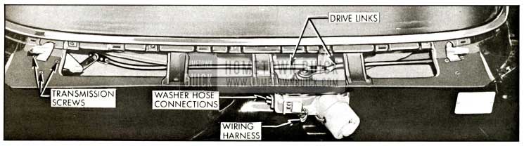
1959 Buick Wiper Transmissions and Links
Cam-o-matic wiper transmissions are not interchangeable with non Cam-o-matic transmissions, nor are right and left side transmissions the same. Although the various transmission links may appear to be similar, linkages are different for Cam-o-matic and non Cam-o-matic.
The cable type drive used in previous years has been replaced with tubular drive links which are located under the air intake grille. The drive links attach to the drive crank arm on the wiper motor shaft and to the wiper transmission operating lever. A special spring retainer clip retains the drive links to the motor drive crank arm. Socket type bearings are used at the transmission end of the drive links. Linkages used on Cam-o-matic are different than those used on the single speed wipers. They should not be interchanged.
1959 Buick Wiper Motor Operation – Electrical
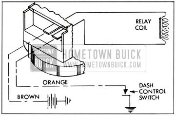
(a) “Lo” Speed – When the switch is turned to the “Lo” position current passes from the live feed (Brown) through the circuit breaker, which is located inside the motor case to the green lead. See figure 1-16.
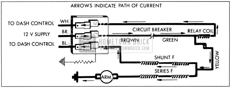
1959 Buick Lo Speed Operation-Wiring Circuit
Current then flows through the relay coil, to the white lead on the terminal connector and to ground through the dash switch to complete the relay circuit. The relay coil is then energized.
As current flows to the relay coil, it also passes through the yellow wire to a split “t” type connection. Current divides with some current passing through the black lead to the terminal connector and to ground at the dash switch to ground out the motor shunt field circuit. The remaining current passes through the motor series field circuit, to the motor armature and to ground. The current flow through the switch to ground is greater than the amount through the armature. Therefore, the motor operates at a reduced speed.
(b) “Hi” Speed – When the switch is turned to “Hi” position, the motor shunt field circuit is no longer grounded due to the switch position. See figure 1-17.
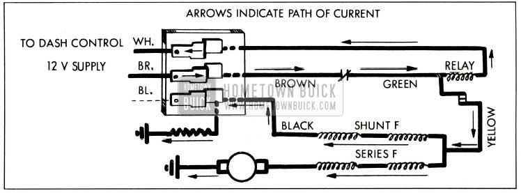
1959 Buick Hi Speed Operation-Wiring Circuit
The majority of current then passes through the motor series field circuit, to motor armature and to ground. Some current does pass through the shunt field windings and to ground through a resistor located on the wiper unit terminal board. However, less resistance is offered to current flow through the series field circuit. Therefore, the greater flow of current through the armature increases wiper motor speed.
(c) “Hi” or “Lo” to Off- When the dash switch is turned to the off position, only the relay coil circuit is opened, stopping current flow through the relay. The motor circuit remains in operation until the relay switch control tab is mechanically opened by the drive pawl as the pawl contacts the stop arm. The relay switch control then opens the motor circuit and the motor stops with wiper blades positioned in park.
1959 Buick Wiper Motor Operation – Mechanical
(a) Motor Switch Turned to “Lo” or “Hi” – Previous to the switch being turned to either “Lo” or “Hi” the drive pawl is in contact with the stop arm. See figure 1-18.
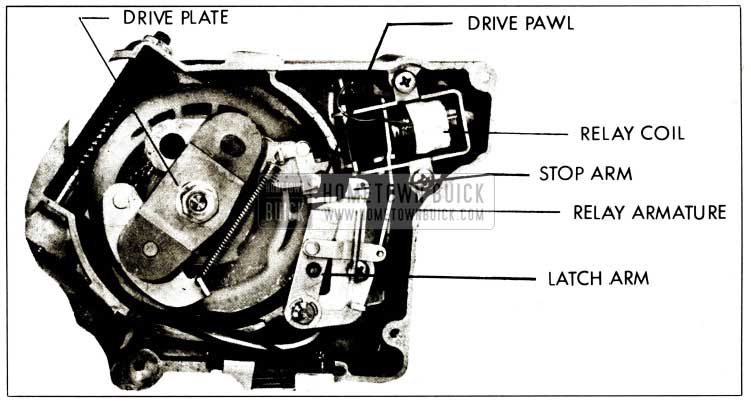
1959 Buick Wiper Motor Off
As the switch is turned on, the relay coil is energized. This moves the armature into the relay and the latch arm out of the path of the drive pawl. At the same time, the motor circuit is also completed.
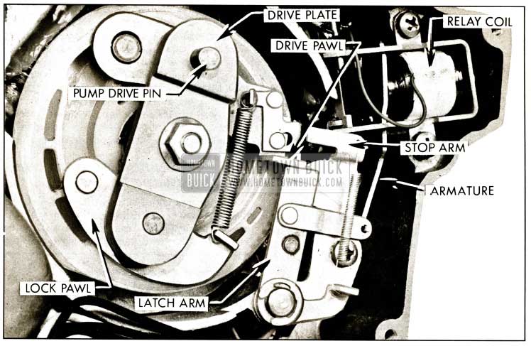
As the motor begins rotating, only the nylon gear and eccentric shaft start to turn. The drive plate is prevented from turning by the drive pawl which is held against the stop pawl. When the nylon gear and shaft have turned approximately 180 degrees, guide pins on the drive pawl and lock pawl drop into their respective pockets in the nylon gear. This action moves the drive pawl away from the stop arm as well as locking the entire drive assembly together. The drive plate, drive pawl, lock pawl, nylon gear and eccentric shaft then turn as a unit. See figure 1-19.
1959 Buick Wiper Motor in Operation
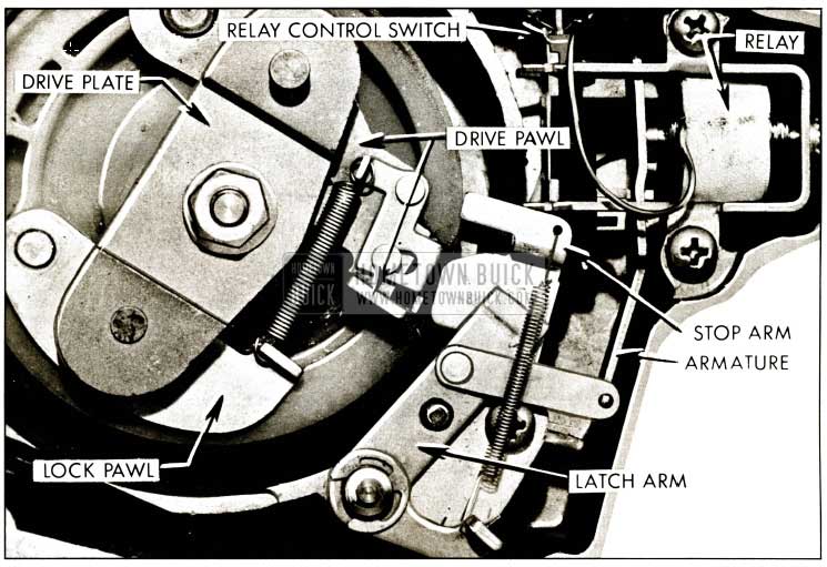
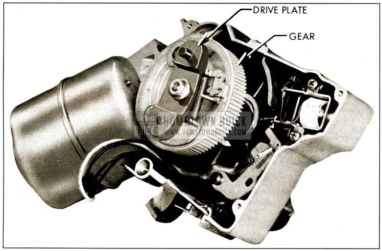
(b) Motor Switch Turned to Off – As the switch is turned to the off position, the relay circuit is opened with the motor circuit remaining closed. The spring loaded latch arm moves out into the path of the drive pawl since the relay is no longer energized. When the drive pawl contacts the latch arm, the drive plate, drive pawl and lock pawl are held from rotating with the nylon gear and eccentric shaft continuing to rotate. See figure 1-20.
1959 Buick Drive Plate Stopped-Motor Running
The guide pins in the drive pawl and lock pawl have been forced out of their pockets in the nylon gear.
The cam type action between the eccentric shaft and drive plate shaft makes the drive plate and related parts move outward toward the relay control switch as the nylon gear and shaft turn. The drive pawl then pushes against the relay control switch tab and opens the circuit to the motor. See figure 1-18.
1959 Buick Washer Pump – Description
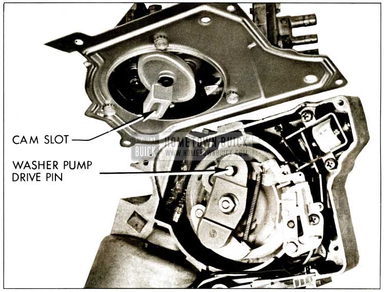
Any time that the motor is turning, a guide pin on the motor drive plate assembly turns an elliptical shaped nylon cam follower in the pump assembly. The cam follower contacts a roller on the ratchet pawl lever. See figure 1-21.
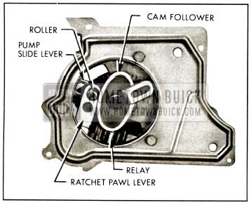
1959 Buick Washer Pump-Motor Side
A torsion spring on the ratchet pawl lever pivot shaft makes the lever and roller follow the nylon cam follower and also puts the ratchet pawl under spring tension.
Two other shafts are located on the ratchet pawl lever, on the side opposite the roller. One of the shafts supports the ratchet pawl, while the shorter shaft actuates the pump slide lever. See figure 1-22.
1959 Buick Washer Pump-Cover Side
The pump slide lever is slotted at one end to receive the short shaft. The other end of the pump slide lever is fitted with a rubber cup type pump diaphragm and a coil spring.
The ratchet pawl is slotted on the end opposite the pivot shaft. The slotted end contacts a nylon ratchet wheel which has 21 teeth. During pump operation, the slot in the ratchet pawl slips over one tooth on the ratchet wheel and rotates the wheel one tooth at a time until the ratchet wheel has been rotated through all 21 teeth or one complete revolution.
The nylon ratchet wheel has a ramp on the side down toward the pump slide lever and also a notch on the top side. The ramp has two functions. First, as the ratchet wheel rotates, the ramp makes contact with a relay armature hair spring to move the spring from under the armature and allow it to drop toward the ratchet pawl. Secondly, it contacts a tang on the pump slide lever which allows the tang to climb up on the ramp and stop the pumping action.
A tang on the pump relay armature falls into the notch on the nylon ratchet wheel when the wheel has made one revolution. This allows the ratchet pawl to slide into a wide slot in the armature, lifting the ratchet pawl away from the teeth of the nylon ratchet wheel.
A relay within the pump housing is energized anytime the washer button is depressed. See figure 1-23.
1959 Buick Washer Pump Wiring Circuit
When energized, the armature is pulled up against the relay to release the ratchet pawl from the armature, allowing the ratchet pawl to engage the ratchet wheel teeth. At the same time, the relay armature hair spring trips to a position under the armature, holding it away from the ratchet wheel and ratchet pawl.
1959 Buick Washer Pump – Operation
Pump action remains the same regardless of whether wiper motor is on when washer button is depressed or if button is depressed to start washer and motor at the same time.
(a) Idling.
With wiper motor turning, the elliptical cam follower is rotated by the guide pin on the ratchet pawl lever. The tang on the pump slide lever is on the high portion of the ratchet wheel ramp, leaving the pump in a cocked position. The pump slide lever is spring loaded by a coil spring next to the rubber cup diaphragm.
With the wiper motor turning, the elliptical cam follower is rotated by the guide pin of the motor drive plate. The pump slide lever is held from pumping by the tang resting on the high portion of the nylon ratchet wheel ramp. The ratchet pawl does not engage the teeth of the ratchet wheel because it is held away from the wheel by the armature. The armature tang is engaged in the slot of the ratchet wheel. The rotating cam follower contacts the roller and moves the ratchet pawl lever back and forth. The ratchet pawl also moves, being connected to the ratchet pawl lever, but no ratchet wheel rotation takes place. The pump is idling.
(b) Pumping.
When the washer button is depressed, the relay energizes. The armature tang moves out of the ratchet wheel slot and the armature hair spring trips under the armature. As the armature moves toward the relay, the ratchet pawl falls free of the armature and engages a ratchet wheel tooth, rotating the wheel one tooth. The distance moved is sufficient for the pump slide lever tang to fall off the ratchet wheel ramp and allow the spring loaded pump to pump the first stroke. The pump completes one pumping stroke for each ratchet wheel tooth movement. After the wheel has rotated approximately 1/2 turn the ramp engages the armature hair spring and moves it out from under the armature. The armature crops and the tang contacts the ratchet wheel but does not affect the ratchet pawl action. After another 1/8 to 1/4, turn of the ratchet wheel, the pump slide lever tang contacts the ramp with a resulting shorter pump stroke. Each succeeding stroke becomes shorter until the nylon ratchet wheel has made one complete revolution and returned to the starting position. At that point, the armature tang drops into the ratchet wheel slot, with the ratchet pawl entering the large slot in the armature and lifting away from the ratchet wheel teeth. The pump is then returned to idling and has completed one pumping cycle.
1-6 1959 BUICK WINDSHIELD WIPER DIAGNOSIS AND TESTING
Testing is divided into two testing sections. The first section is testing to be done with the wiper motor on the car. The second section covers testing with motor removed. See figure 1-24.
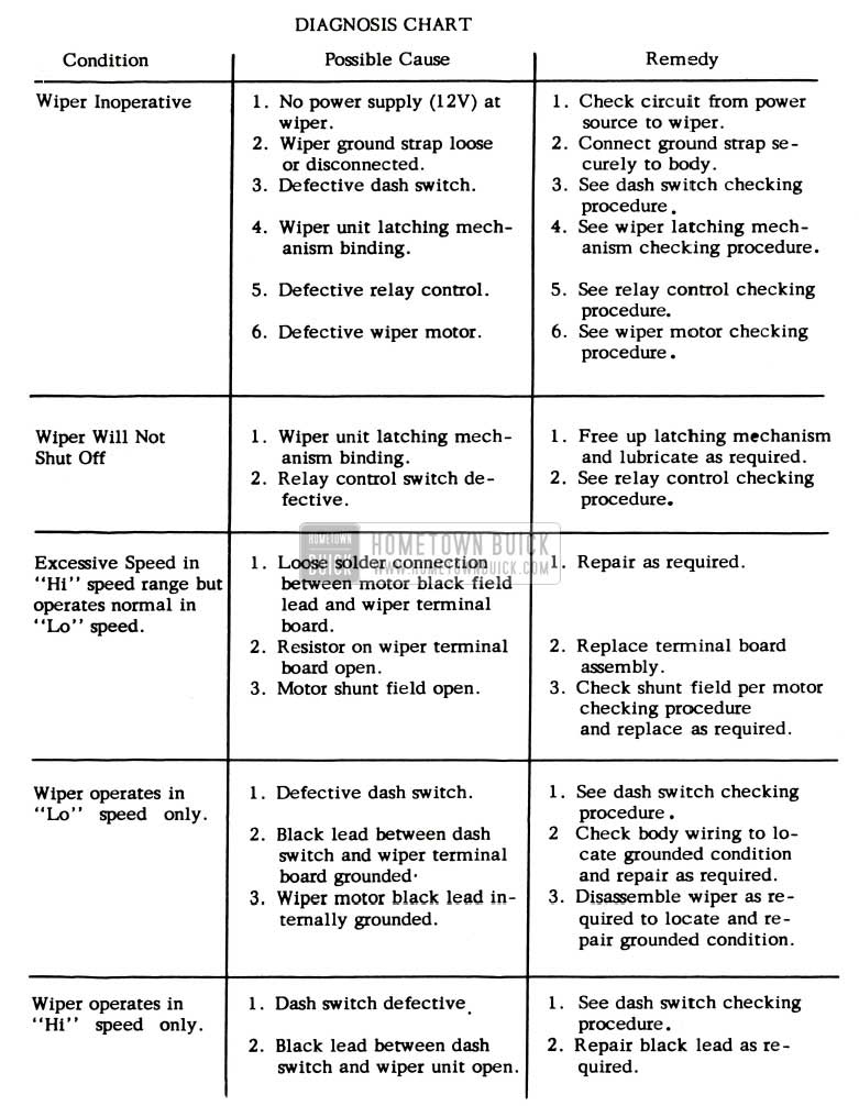
1959 Buick Wiper Motor Trouble Diagnosis Chart
1959 Buick Wiper Motor Installed on Car
Testing with motor installed consists of checking the wiring, switch and wiper linkage.
-
- Make sure wiring is properly connected to the wiper unit and switch.
- Check that wiper unit ground strap is securely connected under wiper unit cover screw and to body.
- With ignition switch turned on, check for 12 Volts at center or No. 2 terminal of wiper unit terminal board. See figure 1-25.
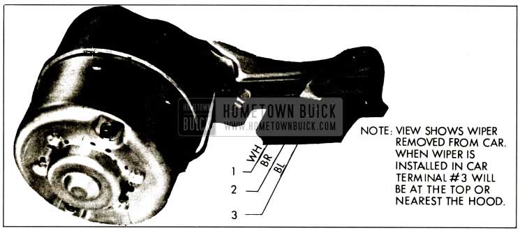
1959 Buick Motor Terminal Connector
If unit is equipped with washer pump, check also for 12 Volts at the brown lead terminal which connects to washer pump.
- Check switch mounting. Loose mounting can cause an intermittent operating condition when using the wiper.
- To determine if switch or wiper is defective try operating wiper independently of switch as follows:
Connect 12 Volt supply to center or No. 2 terminal of wiper terminal board and connect a jumper wire from terminal No. 1 to ground. Wiper should operate in “Hi” speed.
To check “Lo” speed operation connect an additional jumper wire from terminal No. 3 to ground. - To determine if washer pump unit or the washer button switch is defective operate washer pump independently of washer switch as follows:
Operate wiper unit as explained in Step (b) above and connect 12 Volts to either of the washer pump terminals. Connect a jumper wire from the other terminal to ground.
- Remove necessary body parts to gain access to wiper unit crank arm and drive links. Disconnect drive links from the crank arm and manually operate each wiper transmission. The test should determine if transmissions or linkages are binding or damaged.
Wiper Motor Removed
Testing with the motor removed consists of bench testing the relay control-latch mechanism and the motor. Remove gear box and washer pump. Disconnect the yellow lead from the relay control switch.
- Relay Control and Latch Mechanism.
- Manually operate the relay armature to check for a binding or hanging in the latch arm and attaching parts.
- Circuit to Relay Coil-Connect 12 Volt supply to wiper as follows: (+) to center or No. 2 terminal and (-) to housing. Check for 12 Volts at switch terminal to which the green lead is attached. No voltage indicates an open circuit breaker or a broken brown or green lead. (c) Relay Coil-If circuit to relay coil checks out, leave 12 Volt supply connected as explained in Step (b) above and connect a jumper wire from terminal No. 1 to housing. Failure of relay armature to pull in indicates a weak or open relay coil. (Recheck for a binding condition in the latching mechanism.)
- Relay Switch-If Steps (b) and (c) above check out correctly proceed as follows: (1) Leave battery and jumper wire connected as described in Steps (b) and (c) and check for 12 Volts at switch terminal to which the yellow lead attaches. If relay pulls in properly and no voltage reading is obtained a defective switch is indicated.
- Disconnect jumper wire between terminal No. 1 to ground and check that relay armature moves away from coil pole. (Note: If wiper gear mechanism is in full park position, disconnect the coil spring that connects between the gear assembly drive and lock pawls to release the pressure of the drive pawl switch actuator against the switch tab.) Check for 12 Volts at switch terminal to which yellow lead attaches. No voltage reading indicates a defective relay switch.
- Leave voltmeter connected as described in Step No. 2 above and manually push the switch stop tab toward the relay coil. If voltage reading is still obtained a defective switch is indicated.
- Motor Testing.
Disassemble the motor but leave the field coil assembly in the housing.- Check armature for open or short circuit with the use of a growler.
- Use a growler test light to test for grounded commutator bars.
- Inspect the case and brush assembly for worn or defective brushes and brush springs, loose solder connections and dirty or defective circuit breaker contacts.
- Disconnect yellow lead from relay control switch and connect an ohmmeter between the yellow lead and the brush holder to which the internal field lead connects. No reading indicates an open series field.
Next connect the ohmmeter between the yellow lead and the terminal to which the black motor lead attaches. No reading indicates an open shunt field. - Disconnect yellow lead from relay control switch. Be sure steel case and brass ground strap are not touching the housing. Then check between the yellow lead and field lamina with a test light. If bulb lights, field is grounded.
- Bench test motor after assembling in the following manner. Be sure brass ground strap is connected to wiper housing.
- “Lo” Speed-Connect 12 volt supply to center, or No. 2 terminal, and ground housing. Connect jumper wires from No. 1 and No. 3 terminals to ground.
- “Hi” Speed Disconnect jumper wire from No. 3 terminal.
- Stop-Disconnect jumper wires from No.1 and No.3 terminals.
1-7 DISASSEMBLY AND ASSEMBLY
Disassembly of Motor
- Remove the two motor tie bolts. See figure 11-26.
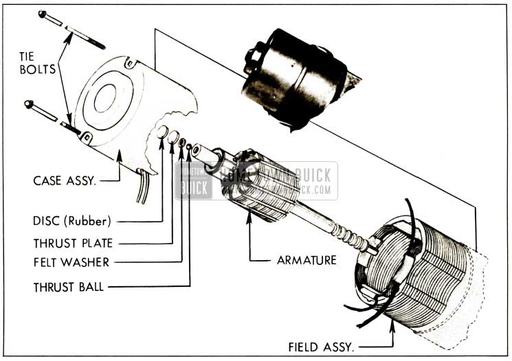
1959 Buick Motor Disassembly
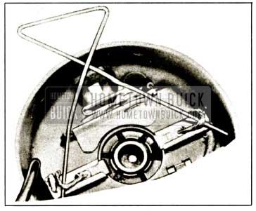
1959 Buick Holding Brush Leads
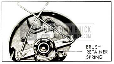
1959 Buick Brush Retainer Spring
- Cut the black and yellow leads that extend through the case assembly rubber grommet in a location convenient for splicing.
- Cut the internal field leads enclosed in black plastic tubing approximately two inches from the brush holder to which they are attached.
- Scribe a reference line along the side of the housing and field for reassembly purposes. (d) Refer to figure 1-29 and remove field from housing as shown.
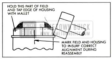
1959 Buick Removing Field Coils
Assembly of Motor
- Install field assembly as follows:
- Shorten as required and splice the replacement field leads to those leads cut in Steps 8(a) and 8(b) under motor disassembly.
- Scribe a reference line on the replacement field in the approximate same location as the one scribed on the original field (Step 8(c) under motor disassembly).
- Align the field and housing according to the reference lines and start the field in the housing. A further check to insure alignment is shown in figure 1-30.
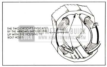
1959 Buick Aligning Field Coils
NOTE: It may be necessary at this point to rotate the armature slightly before the worm will engage with the worm gear.
Disassembly of Relay Control and Catching Mechanism
- Remove the four screws which secure the gear box cover or washer pump assembly to the gear box.
- Disconnect coil spring, remove “E” ring and lift the latch and follower assembly off the pivot pin and relay armature. See figure 1-31.
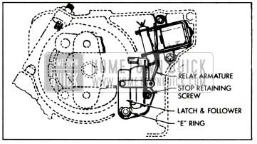
1959 Buick Disassembly of Relay and Latch
Assembly of Relay Control and Latching Mechanism
Solder existing green and yellow wiper leads to relay control switch and solder the relay coil lead to the wiper unit terminal board as shown in Figure 1-32.

1959 Buick Relay Coil Wiring
Disassembly of Drive Gear Mechanism
- Remove the crank arm retaining nut. See figure 1-33.
1959 Buick Drive Gear Mechanism
Assembly of Drive Gear Mechanism
- Assemble lock and drive pawls to the shaft and drive plate assembly as shown in figure 1-34.
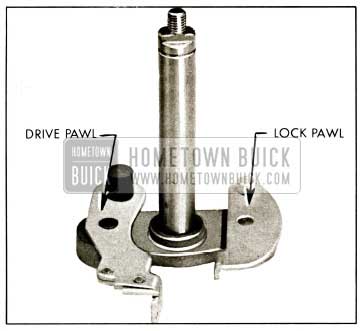
1959 Buick Lock and Drive Pawl Assembly
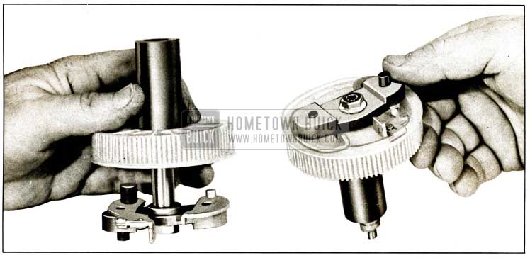
1959 Buick Installing Pawls and Shaft into Gear
1959 Buick Installing Gear and Shaft Assembly
Washer Pump Assembly
- Washer pump assemblies are not to be disassembled. To replace the assembly, proceed as follows:
- Remove wiper unit from car.
- Remove the four (4) screws that secure the washer pump and cover assembly to the gear box. See figure 1-37.
1959 Buick Washer Pump Replacement
1-8 1959 BUICK WINDSHIELD WIPER ADJUSTMENT
Armature End-Play
- Loosen adjusting screw locknut and tighten the adjusting screw until finger tight.
- Back off set screw 1/4 turn and tighten locknut.
Gear Assembly End-Play
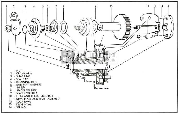
- Gear assembly end-play is controlled by end-play washers located between the seal cap and shield. See figure 1-34. End-play should be .006.
1-9 1959 BUICK WIPER SPECIFICATIONS
Voltage Supply – 12 Volts
Current Draw
- Bench Check (no load) – 3 to 4.5 Amps.
- Installed in Car (wet windshield) – 3.5 to 5 Amps.
Blade Wipes Per Minute
- “Lo” Speed-35 to 45.
- “Hi” Speed-70 to 85.
1-10 REMOVAL AND REPLACEMENT OF ASSEMBLIES
1959 Buick Wiper Motor Assembly
- Remove
- Disconnect wire connectors from motor and pump.
- Pull washer hoses loose from pump.
- Remove left side air intake grille.
- Remove spring retainer clip from wiper motor shaft.
- Lift transmission drive links off motor shaft.
- Remove four wiper motor bolts.
- Replacement
- Reverse Steps (f) through (a).
1959 Buick Wiper Transmission
- Removal
- Remove wiper blade and arm, shaft and escutcheon retaining nuts and escutcheon from transmission shaft. See figure 1-38.
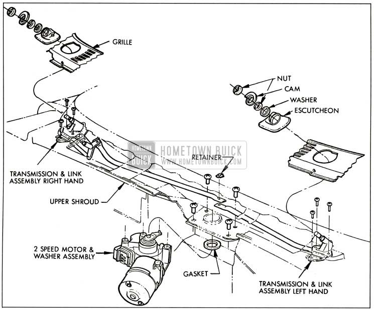
1959 Buick Wiper Assemblies-Exploded View
- Reverse Steps (e) through (a).
Leave A Comment
You must be logged in to post a comment.